Axis Configuration
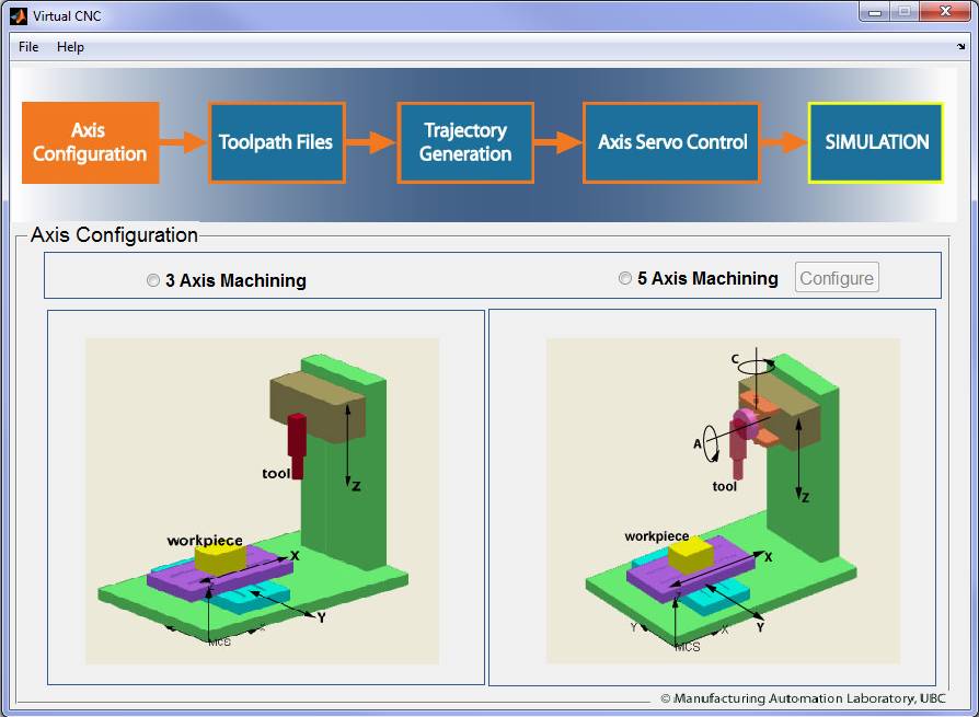
The Axis Configuration module has two options: 3 Axis Machining and 5 Axis Machining.
Nothing needs to be configured for 3 axis machine.
In the 5-Axis Machine Configuration Module, you'll configure and build the kinematical structure of a machine tool for your CNC system and check if the machine structure configuration is feasible.

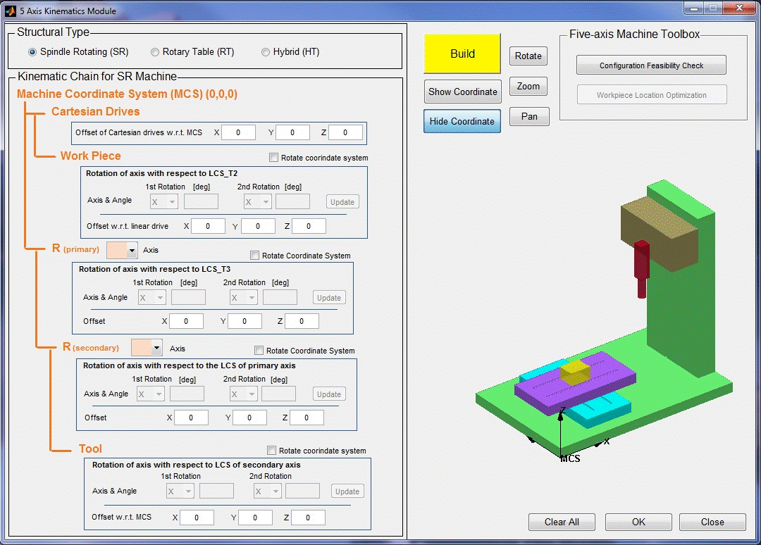
To configure a 5 axis machine, select the ‘5 Axis Machining’ radial button first, and then click the ‘Configure’ button to open the 5 Axis kinematics Module configuration interface.

The 5 Axis machine must be configured with the following five steps.
Step 1: Selecting the Structural Type
There are three options for the structure type: Spindle Rotating (SR), Rotary Table (RT) and Hybrid (HT).
l With the Spindle Rotating (SR) structure, both rotary axes are built on to the spindle part so the orientation motion is driven by the spindle;
l With the Rotary Table (RT) structure, both rotary axes are built on to the linear XY table and the workpiece is fixed on top of the rotary table. The orientation movement is driven by the workpiece;
l As a hybrid form of the above structures, Hybrid (HT) is designed as one rotary axis built on the spindle and the other on the XY table.
Step2: Configuring the Kinematic Chain
Then you should specify the ‘Kinematic Chain’ based on the machine structure type selected on the step 1. The Kinematic chain relates 6 coordinate systems. The ‘Machine Coordinate System’ contains 5 subsystems: ‘Cartesian Drives’, ‘Work Piece’, ‘Primary’, ‘Secondary’ and ‘Tool’. Particularly, the Primary and Secondary systems should be set with a rotary axis from X, Y and Z.
After the rotary axes are specified, the offset and rotation of each subsystem can be set. The constant offset values for X, Y, Z should be set based on its reference system. Similarly, if there is a constant rotation between the current system and its reference system, then the “Rotate Coordinate System” check box should be chosen. The 1st and 2nd rotation axis and its angle value can then be configured separately.
Step3: Building the 5 Axis Machine
The configuration results can be displayed by clicking “Build” in and the machine with rotary axes will be presented.
The coordinate of each system can be turned on or off by clicking the ‘Show Coordinate’ button and the ‘Hide Coordinate’ button. The ‘Rotate’, ‘Zoom’ and ‘Pan’ buttons will help you view the virtual machine structure better.
Step4: Checking the Configuration Feasibility
It is necessary to check the configuration feasibility before proceeding by clicking the ‘Configuration Feasibility Check’ button.
Step5: Save and quit
If the configuration is feasible after step 1-4, you should click the ‘OK’ button to save the configuration and click the ‘close’ button to quit.