Virtual CNC Real Time Implementation Quick Start Guide
A sample application of the real time implementation will be shown below for a 3 axis Fadal machining center.
Step 1: Loading a Model
Open VCNC and load the example file located in Virtual CNC Examples/Ex01_Kinematic Configurations\Ex01A_3 Axis Rigid Drive Example.vcnc. This is done by going to File->Open in VCNC.
Step 2: Simulating the Model
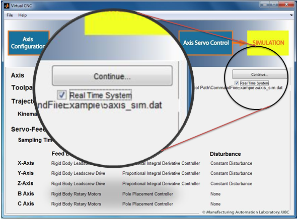
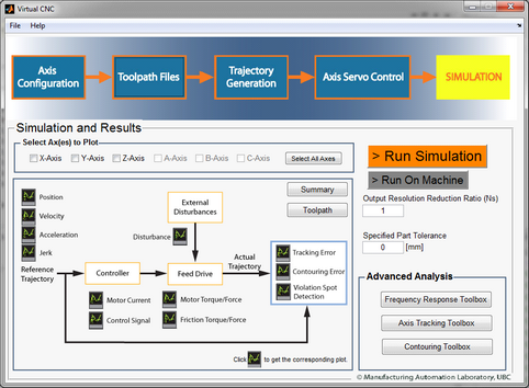
The settings within VCNC can be changed, however the default setting should work for the example. After making any changes to the system parameters the Run Simulation button can be pressed, located in the Simulation tab page. After clicking the Run Simulate button check the Real Time System checkbox, as shown below. Then click Continue as you regularly would for running a simulation.
Note: If the system is to be tested on a real machine the computer running VCNC must have a dSPACE DS1103 device connected to it. This system will build the controllers and trajectory into a C-coded file that is automatically loaded to the dSPACE board. The dSPACE board needs to be connected to the machine using the connection mapping shown in the table below
Real Time dSpace Connector Map
DS1103 Connector |
Machine Connection |
Description |
DACH1 |
X-AXIS CONTROL (-10 to +10 volts) |
Voltage to control axis |
DACH2 |
Y-AXIS CONTROL (-10 to +10 volts) |
Voltage to control axis |
DACH3 |
Z-AXIS CONTROL (-10 to +10 volts) |
Voltage to control axis |
DACH4 |
A-AXIS CONTROL (-10 to +10 volts) |
Voltage to control axis |
DACH5 |
B-AXIS CONTROL (-10 to +10 volts) |
Voltage to control axis |
DACH6 |
C-AXIS CONTROL (-10 to +10 volts) |
Voltage to control axis |
DACH7 |
Spindle Control (-10 to +10 volts) |
Voltage to control spindle RPM |
Inc1 |
X-AXIS FEEDBACK |
Encoder Feedback |
Inc2 |
Y-AXIS FEEDBACK |
Encoder Feedback |
Inc3 |
Z-AXIS FEEDBACK |
Encoder Feedback |
Inc4 |
A-AXIS FEEDBACK |
Encoder Feedback |
Inc5 |
B-AXIS FEEDBACK |
Encoder Feedback |
Inc6 |
C-AXIS FEEDBACK |
Encoder Feedback |
Digital I/O PIN 1 (Input) |
Spindle Feedback |
5Volts = error, 0V = okay |
Digital I/O PIN 9 (Output) |
Spindle on/off |
5Volts = on, 0Volts = off |
Step 3: Configuring the Real Time Build Information
Once the simulation has been run with the Real Time System checkbox clicked, the Run On Machine button can be pressed to start the process of preparing the code for real time testing .
Step 4: Configuring Build Parameters
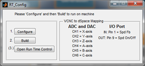
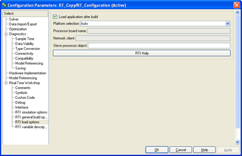
First the Configure button in the RT_Config window needs to be pressed to configure the real time build parameters. This will open the Configuration Parameters window. The default settings should generally be correct and the OK button can be pressed to confirm and return to the RT_Config window.
Step 5: Building the Real Time Implementation
The Build button in the RT_Config window can then be pressed. The system will then build, compile, and load the C code onto the dSPACE board. Once it is complete it will open a Spindle_Configuration dialog window.

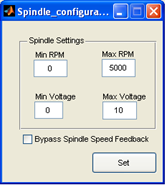
Step 6: Spindle Control Configuration
The spindle RPM is set by the dSPACE outputting a voltage. The relationship between the RPM and voltage is assumed to be linear. Therefore, the minimum and maximum RPM range of the machine is required as well as the minimum and maximum voltage that the machine is expecting for the Spindle RPM control. Linear interpolation is then automatically used to determine the required output voltage. If there is no spindle feedback available the Bypass Spindle Speed Feedback checkbox can be checked. This will disable the feedback and the controller will assume the spindle is operating at the requested RPM. The Set button can then be pressed and the real time GUI window will open (Labeled as VCNC_RT_Interface).

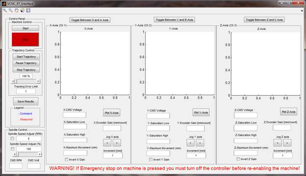
Step 7: Using the Real Time Interface to Control the Machine
The real time GUI is used to control the machine using the designed controller and trajectory. The table included below explains the operation of each button.
Real Time GUI Description
Graphical User Interface Function Name |
Function Description |
Machine Control - Start |
Starts the controllers running on the machine |
Machine Control - Stop |
Stops the controllers therefore stopping the machine via software |
Trajectory Control Start Trajectory |
Start or Resume the programed trajectory |
Trajectory Control Pause Trajectory |
Pause the programmed trajectory at its current position WARNING: This will stop the machine in its current position suddenly, causing a large deceleration and jerk |
Trajectory Control Stop Trajectory |
This stops the trajectory, similar to Pause, however it resets everything so that it will start from the beginning next time |
Trajectory Control Feed Rate Override (below Stop Trajectory) |
Allows the trajectory speed to be adjusted from 0 to 200% of original trajectory speed (100% is original speed) |
Trajectory Control Tracking Error |
Safety to limit Tracking Error, if individual axis exceeds limit the output voltage is shut off |
Save Results |
Save data collected during Trajectory execution (output formats are csv and mat) |
Spindle Control Spindle Speed Adjust(RPM) |
If this option is selected it adds the entered spindle RPM to the originally commanded RPM (Can be negative) |
Spindle Control Spindle Speed Adjust(%) |
If this option is selected it scales the originally commanded RPM by the entered value (0 to 200%) |
Spindle Control CMD RPM |
Displays the currently commanded RPM |
Spindle Control CMD Volt |
Displays the voltage currently sent to the machine for RPM control |
Axis Control Toggle Between |
Allows the user to switch between the axis (i.e. X or A, Y or B, Z or C) |
Axis Control CMD Voltage |
Displays the current voltage being sent to the drive amp |
Axis Control Saturation Low |
Sets minimum output voltage that can be sent to drive amp |
Axis Control Saturation High |
Sets maximum output voltage that can be sent to drive amp |
Axis Control Maximum Movement (mm) |
Sets absolute maximum movement that that axis can move from starting position, when exceeded output is set to 0 volt |
Axis Control Invert Gain |
Set the axis feedback gain to be inverted WARNING: Do not switch during operation, unstable behaviour will occur! |
Axis Control Plot Axis |
Shows a detailed plot of that particular axis |
Axis Control Encoder Gain[mm/count] |
Displays the current encoder gain [mm/count], can also be used to set a new encoder gain |
Axis Control Jog axis |
Moves the axis using the controller amount specified by the Increment box |
Axis Control Increment[mm] |
Sets the jog increment (unit is mm) |